

S7021 - pulse data logger with counting and binary inputs
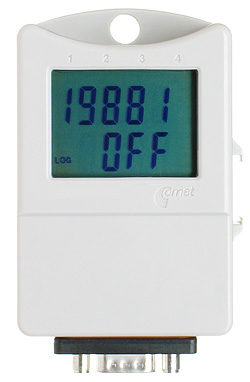
Pulse data logger S7021
Main applications of pulse data logger:
- record of pulses from water meter, gas meter, electrometer, flow meter, revolution counter
- time event record from binary signal (e.g. door opening/closing .. )
- production monitoring
- long term field measurement
Advantages of pulse data logger:
- counter reading is possible to display in real value, range of the LCD display is 19999, after exceeding of displayable value only lowest places are displayed
- two modes are enabled: after counting of maximum value counter stops or overflows and counts again, counter reset enabled from the PC
- in the record is possible to indicate counter state or counter state increment between logging intervals
- record from binary input contains date and time (resolution of 1 s) when change of input logic level appeared and its logic state
- record from binary input can be disabled
- it is possible from the PC to assign both logic states of binary input a description, which is displayed on the record – on the LCD logic states are always displayed as ON ( contact closed) and OFF (contact opened)
- variability of connection to the computer - USB, RS232, Ethernet, GSM modem
- permanent connection to the PC enabled, data is possible to download even during logging
- dual level alarm is enabled for counting input, alarm is indicated by blinking of the value on the LCD display
- low power consumption from battery, easy replacement of the battery
- logging start/stop is enabled: at certain time and date programmed from computer, by external signal connected to binary input or by delivered magnet
- also special logging mode is enabled, when logging runs only, if counter value is out of adjusted alarm limits
- input pulse signal is recalculated and displayed in real measured physical units by means of the PC software
- extremely low consumption from the battery, indication of remaining battery life, easy battery replacement
- robust watertight case, easy installation, locking enabled
- each logger is possible to describe with text of maximum 32 characters
- each channel is possible to describe with text of maximum 16 characters
- password protection is enabled to prevent unauthorized manipulation with logger
| TECHNICAL PARAMETERS | |
|---|---|
| Counter range – user selectable: | in 16bit mode: 0 to 61 695 pulses, memory of 32 504 records in non-cyclic mode in 32bit mode: 0 to 2 021 654 527 pulses, memory of 16 252 records in non-cyclic mode |
| Input signals: | from potential-less contact or two state voltage signal |
| Parameters of counting input: | minimum pulse duration: 1 ms (shorter pulses may not be recorded) maximum frequency: 500 Hz current through closed contact: 30microA, maximum voltage across opened contact: 3.6V LOW voltage level: 0 to +0.2V (current from input max 30microA) HIGH voltage level: +3.0 to +30V (current to input max 100nA) |
| Parameters of binary input: | minimum pulse duration: 500 ms (shorter pulses may not be recorded) maximum frequency: 0.5Hz (i.e. maximum 5 pulses in 10s) current through closed contact: 3microA, maximum voltage across opened contact: 3.6V LOW voltage level: 0 to +0.2V (current from input max 3microA) HIGH voltage level: +3.0 to +30V (current to input max 100nA) |
| Operational temperature range: | -30 to +70°C |
| Real time clock: | year, leap year, month, day, hour, minute, second |
| Data logging interval of counting input: | adjustable from 10s to 24hours |
| Refresh of display and alarm state: | every 10 s |
| Data logging modes: | noncyclic – logging stops after filling the memory cyclic – after filling memory oldest data is overwritten by new |
| Built-in connector for input signals: | male Canon 9 pins |
| Dimensions without connector, | 93x64x29mm |
| Weight: | 130g |
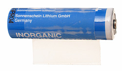
| Power: | Lithium battery 3,6V, size AA, typical life 3 years, indication of remaining life |
| Protection: | IP67- protected against influence of temporary immersion into water |
| Warranty: | 2 years |
Data logger accessories
Battery is included in delivery. No other accessory is included. For basic use it is necessary to order at minimum a COM adapter or USB adapter or LAN adapter for communication with computer, optionally a start/stop magnet, if needed to control logging the other way than directly from computer or by external binary signal. Also connector for input signals connection is necessary to order.
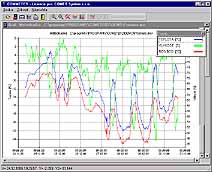
Anytime it is possible to download free basic Windows program for data logger. Program enables to control all logger functions and viewing and printing of record in numerical and simple graphic format. It is possible to export recorded values to dbf or txt formats for further analysis.
| OPTIONAL ACCESSORIES | ||
|---|---|---|
|
SWR004 | Windows optional software for data logger - color printing, vertical and horizontal zooming of graphs and other functions. |

|
DBL |
Database program DBL Logger Program for work with data from Comet loggers. Program enables i.a.: - To set locally the GSM modem via RS232 link by means of the QMS2901 cable. - To view selected channels from any Comet logger together with selected channels of other Comet loggers. - Measurement from different Comet devices is possible to combine in one table or graph. - To choose any time interval for analysis. - Print, export to PDF - table and graph. - Uses freeware database server MySQL |
|
SW100 | CD with free PC program |
|
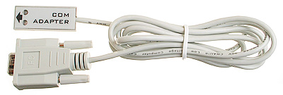
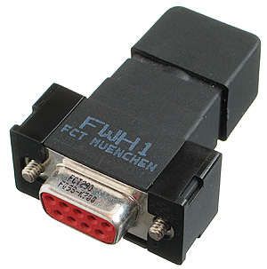
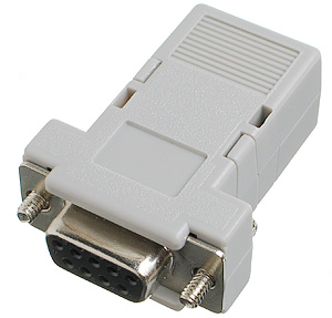
LP002 | COM adapter for communication with personal computer via RS232 serial port |

|
LP003 | USB adapter for communication with personal computer via USB port |
|
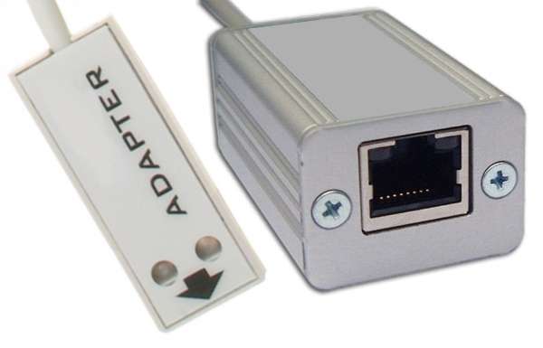
LP005 |
LAN adapter - external converter for communication with the PC via Ethernet, including ac/dc adapter 230Vac/5Vdc. Exceeding of adjusted limits is alarmed by sending e-mail message or trap. More information in manual of Ethernet interface in pdf |
|
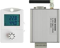
New ! Wireless communication with loggers via GSM |
|
|
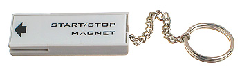
LP004 | start/stop magnet |
|
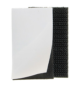
MD036 | self adhesive Dual Lock for easy installation |

|
F9000 | wall holder secured against unauthorized removal |
|
A4203 | spare Lithium battery 3.6V size AA |
|
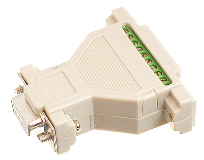
K0921 | watertight female connector Canon 9 pins for connection of input signals, protection IP67. |
|
K0925 | female connector Canon 9 pins for connection of input signals, protection IP20. |
|
K0945 | adapter with terminals for easy connection of input signals, protection IP20. |